Hey guys!! Since this was my first project I tried to make my project as simple as possible for my sake.But for me since I was new to this field I made many mistake and learnt a lot from them.If you want to try to make this project please visit this link
https://circuitdigest.com/microcontroller-projects/arduino-wattmeter-to-measure-voltage-current-power-consumption as it contains the stepwise procedure.But I am going to tell you the errors you will make if you blindly copy the website and try to make it on your own!!.If you are familiar with Arduino no issue at all. But if this is your first time using it I would suggest you to go through some LED tutorials ,as they are easy to understand as well as they give u a rough idea about arduino. Okay..since the website i have given will give you all the details of making this project I won’t waste my further time on instructing how to make.
Lets begin :-
DAY 1: Planning!!
Guys this might sound stupid but yes! you have to plan your project even if you know the procedure ,my suggestion is that if you have any friend who is interested in this type of project…collaborate with him share your ideas,think where you can use this project,plan your expenses,make a time schedule and follow that
MISTAKE I DID:- In my case i was alone,nobody helped me ..so i had to struggle a lot for getting ideas,i spent a lot of money on buying components,there was no time management at all!!
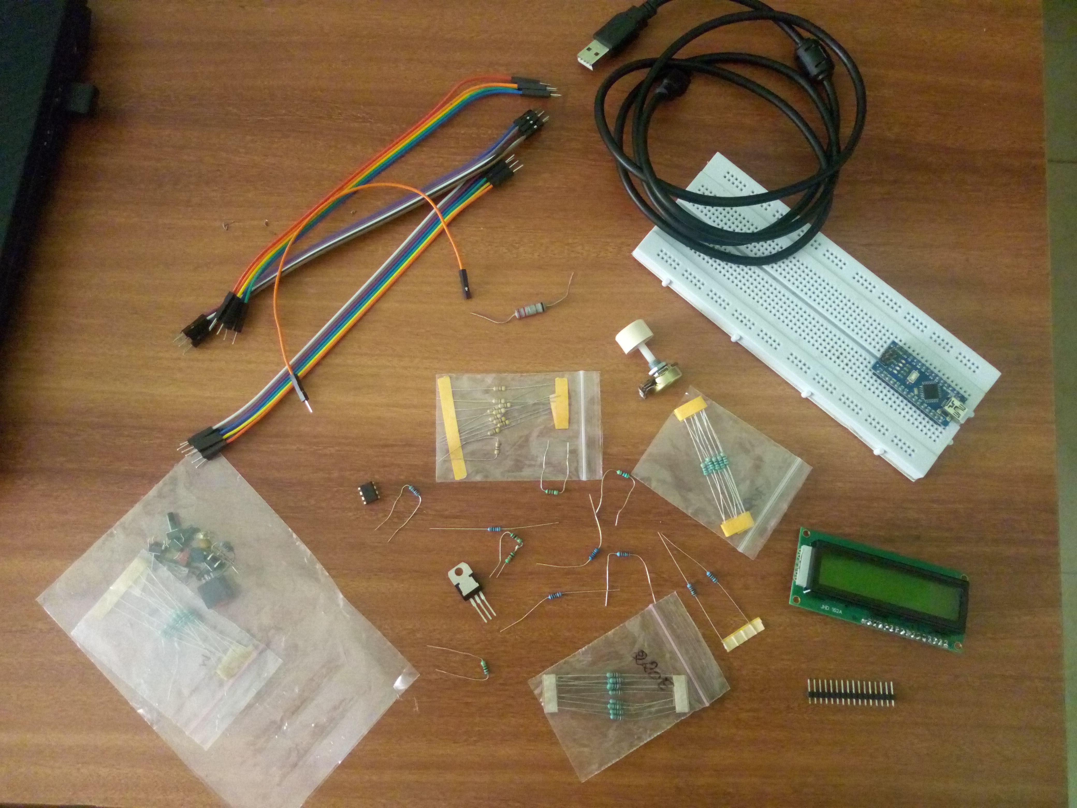
DAY 2: Getting Components!!
Don’t rush!! Write each and every component required and then buy it.If you got any market place for that stuff check it out there instead of searching online,Market usually have lower price than online.But if you are getting cheap no issue.Please make sure you know each and every component structure and additional components if required with them.
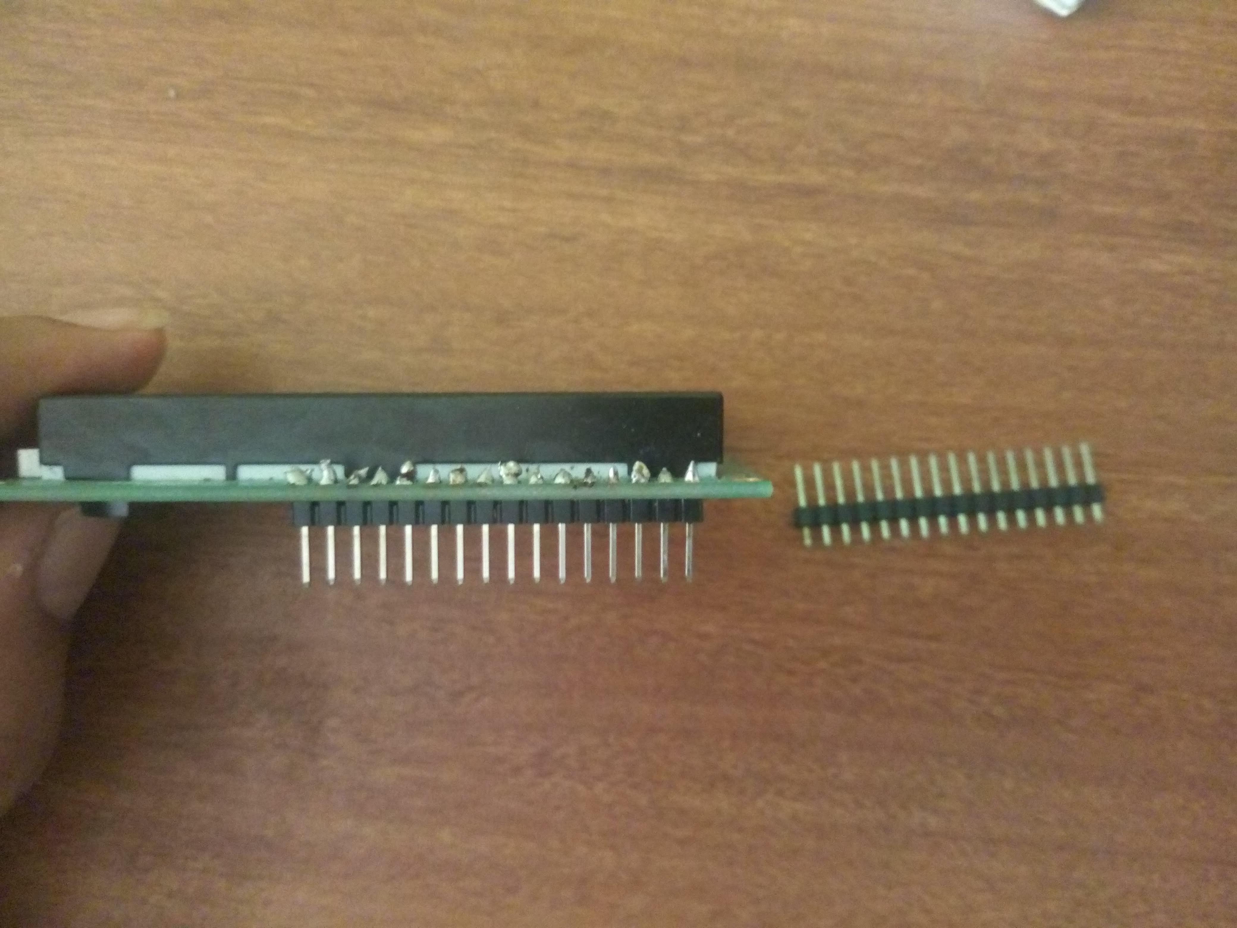
MISTAKE I DID:-I went market without writing anything ,thinking its there on the internet ,but unfortunately the shopkeeper won’t wait for you to see and tell each component,another thing was that we need 16 pins for your LCD screen(if you know please ignore) .These pins are not attached to LCD when you buy it ,you have to purchase it additionally and solder it on your LCD.I hope you know how to solder..if u don’t here’s a link https://youtu.be/E9NIN49iiCc (i am not promoting them i am just helping you)
DAY 3: Making the Circuit!!
Here comes the difficult part if you don’t know or never made a circuit before.Here major part lies in understanding the function of components how it works and why was it necessary to include it ,understand the logical circuit,connection and functionality.Its better to make the circuit only with the Arduino and LCD.It is because ,you just have bought this two and don’t even know whether they are working or not. connect the LCD with Arduino and run a simple hello world program to make sure that work properly.The LCD might give you some difficulty,check the soldering of the pins, the connections.
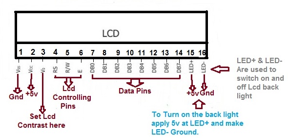
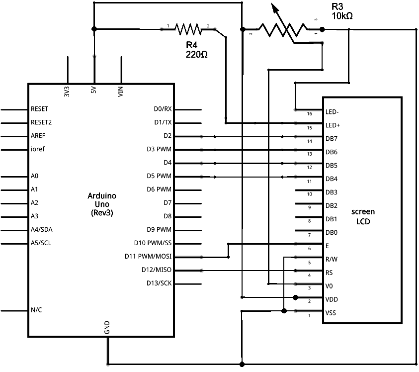
this link will give you tutorial for LCD https://www.arduino.cc/en/Tutorial/HelloWorld run some other display programs to get familiar.
MISTAKE I DID: Soldering had some issues,also the connection with the arduino was wrong.So everytime i used to run the code the backlight was ON but no output was shown,kindly check your connection if you are getting error .if it doesn’t match with the online symptoms then maybe you need to replace it.if you don’t get the output even on several attempts ,don’t loose hope,try some time later.
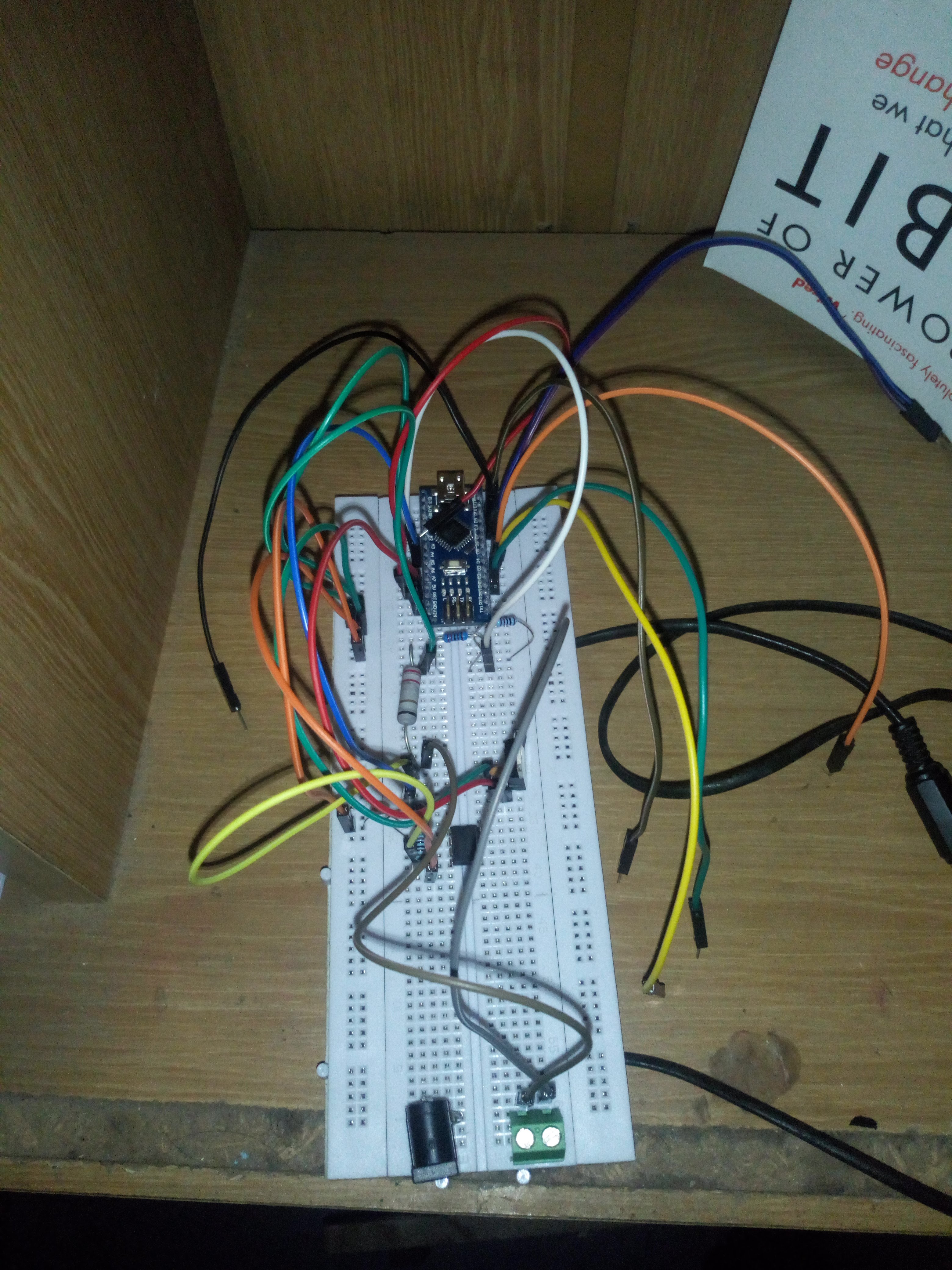
DAY 4:Assembling everything!!!
Now that you know that every component is functional ,move to assembly part,check each and every connection until you are satisfied.Don’t hesitate to disassemble it you will learn a lot about the connection.
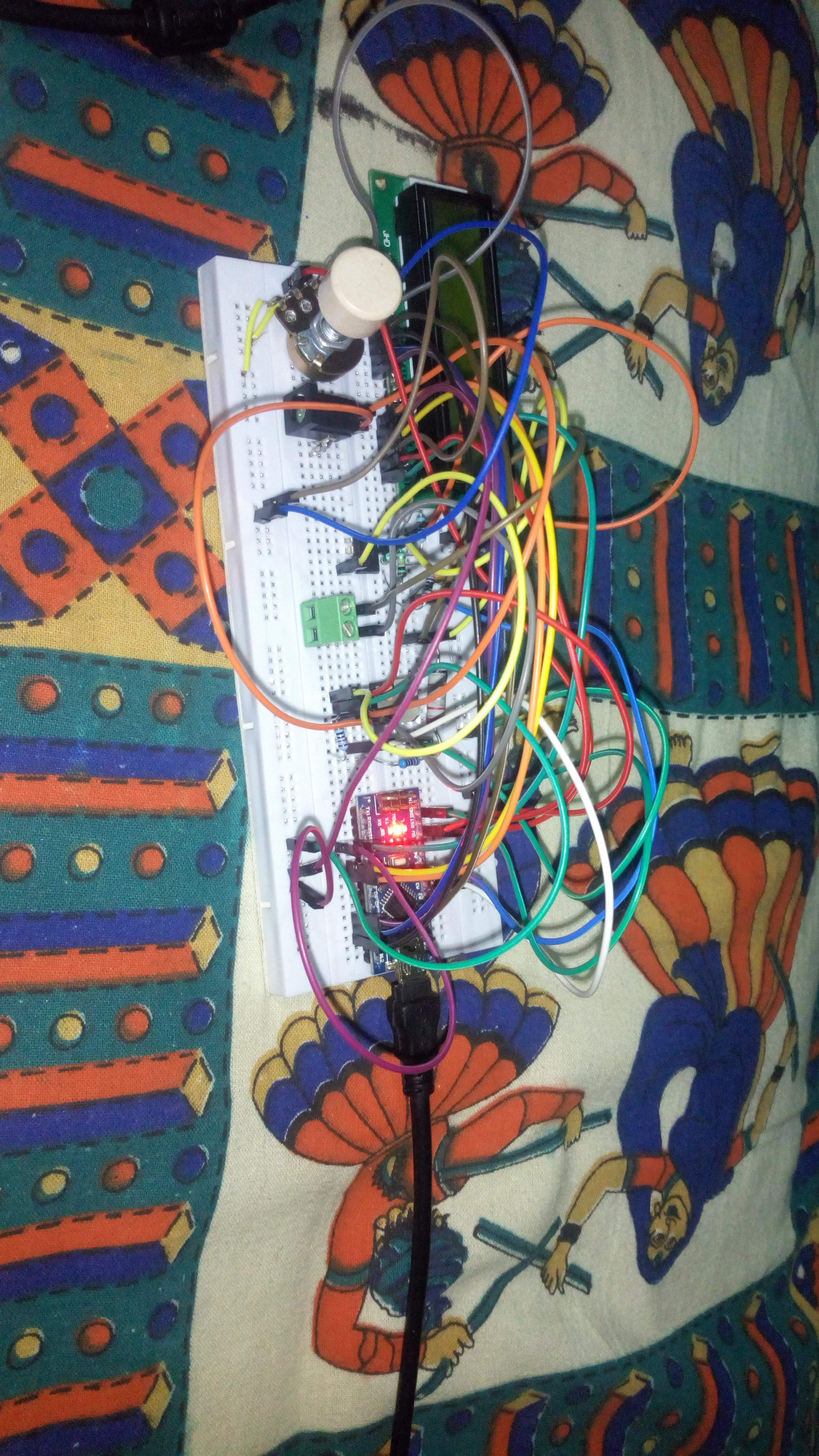
DAY 5: Testing the circuit!!
At last we are here..but wait this is not the end .We don’t know whether our circuit might work or not..the program is uploaded.But i have not given any load..wait the circuit doesn’t seem right!!! Something is not working!!! chill it happens everyone gets an error , if you don’t get what will you learn?? debug the code,understand where you went wrong,Do you need to change the code according to your needs?CHANGE IT!! don’t be afraid, you don’t have anything to lose (don’t worry your arduino won’t blast neither will your LCD they have current regulator inside them!!)check the connection of your assembly ,is it correct or you are just assuming it is correct ,dig deeper..if it still persists disassemble it and do it again.
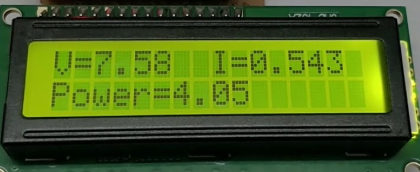
**MISTAKE I DID:**My connections were totally wrong and i was assuming it to be correct.I disassembled and assembled about 12 times ..this is the pic of 4th time..my power value was still wrong !! XD .But try and try until you succeed
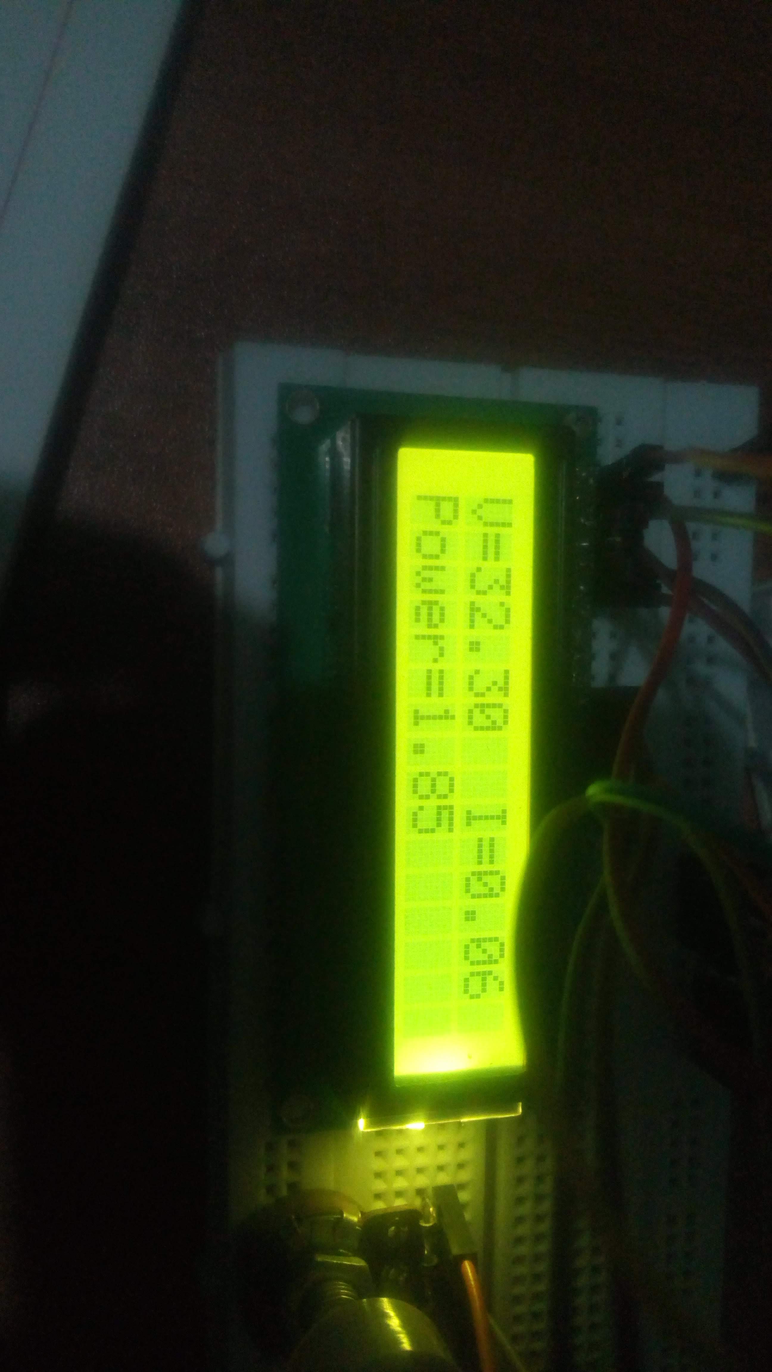
DAY 6: Finally i made it!!
After discovering so many wrong ways i got the correct one .sorry guys i just have the pic of the reading not whole circuit.But if you are able to achieve its great!!

Benefit i received from this project:
- learnt about working of LCD in arduino
- learning about opamp
- learning transistor
- Won my Project Based Learning competition with first prize of INR 3K(since my team project was not working ,i attached my circuit to the project and took it as load resistance.since mine worked fine.The judges got impressed with explanation and we won!!